Included in the Box
The DockStar's Smart Thruster system is comprised of two parts. The first part is the actual Smart Thruster. This unit is self-contained with its own batteries and wireless control system. It attaches to the boat by sliding onto a T-track assembly that in turn is mounted to the boat. This T-track assembly is the second part to the thruster system. All bow and stern installations use the same Smart Thruster, but use different T-track assemblies. There are two T-track assembly configurations for mounting to bows and four configurations for mounting to sterns. Which configuration is used is dependent on the particulars of the boat and on the preferences of the owner. We will discuss what is included with the Smart Thruster and what is included with each of the six T-track assembly kits.

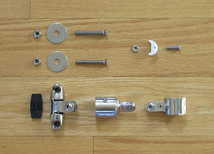
The contents of the Smart Thruster box are shown to the left. The thruster is shown in the middle. The propellers, propeller shear pins, and propeller nuts are shown above the Smart thruster's motors. In the lower left above the propeller nut and shear pin is a plastic spoke wrench for tightening the propeller nuts. For detailed instructions on installing the propeller please see the Operators Manual on our manuals page.
Above the propeller nut wrench is the battery charger. This plugs into a standard USA AC socket on the input side and into the Smart Thruster's charger port on the output side. The AC power cord for the battery charger is shown to the left of the charger. Please see the Operations Manual on our manuals page for how to use the recharger.
In the upper left hand corner is the thruster's lanyard, the antenna, and the pairing plug. The antenna needs to be screwed onto the face-plate of the Smart Thruster. The pairing plug is used to pair the radio transmitter with the Smart Thruster. The transmitter and thruster come already paired for use as a bow thruster. To pair them for use as a stern thruster or to pair them with another Smart Thruster please see the Operations Manual on our manuals page.
In the upper right hand corner of the picture is the neoprene cover for the top of the Smart Thruster. This cover should be kept over the Smart Thruster face plate when ever the thruster is not in use. This helps protect the thruster from UV and moisture.
Below the neoprene cover is the hand held radio transmitter, a spare battery for the radio transmitter, and the transmistter's neck lanyard. This radio transmitter used to control the Smart Thruster in operation as explained in the Operations Manual.
Please keep the spare battery and pairing plug mentioned earlier in a safe place for future use.
Bow Installation T-track Kits
There are two T-track Assembly Kits available for mounting the Smart Thruster to the bow of a boat. The kits are very similar. The main difference is the length of the T-track. Some boats require longer tracks than others. The longer T-track Assembly Kit supports a stainless tube length of 55" to 71" and T-track lengths of 67”, 64”, 61”, 58”, 55”, and 52”. The T-track is cut in increments of 3" because that is the pitch of its mounting screws. The shorter T-track Assembly Kit supports a stainless tube length of 45" to 64" and T-track lengths of 49”, 46”, and 43”. Please see the "Bow Installation Guide" on our manuals page for detailed information on how these assemblies are installed on your boat.
The two pictures on the left (below if you are viewing on a mobile device) show the components included in the longer bow T-track Assembly Kit. On the far left is the 67" T-track partially mounted to the 71" stainless rail. The last 5 holes at the top have not yet been drilled or mounted. This is to allow the user to shorten the T-track in increments of 3" to fit the needs of their boat. Please see the "Bow Installation Guide" for more information.
-
On the far right is a three-foot-long 8-32 threaded rod that is used to hold the T-track mounting nuts in position inside the stainless tube. This is explained in the Installation Guide.
-
To the left of that at the top of the picture are a standard bimini hinge and an end cap for mounting the top of the T-track assembly,
-
Below that is an assortment of 10-32 screws, washers, and lock nuts that are used for mounting the top and bottom hinges to the hull. Not all of these screws and hardware are used. We provide a variety so you can best match the hardware to your boat's needs.
-
Below the mounting hardware is a single end-cap nut holder with a pan head screw and nut. These are used to secure the top end-cap to the tube once the tube is cut to the proper length for your boat.
-
Next, there are five sets of nut holders, flat-head screws, and nuts for securing the desired length of T-track to the stainless tube. Please see the Bow Installation Guide for information on how these are used.
-
At the bottom of the picture to the left of the long threaded rod is the pivoting deck hinge for attaching the bottom of the T-track assembly to the bow of the boat.
-
To the left of the 10-32 screws and hardware are a pair of cleats and a few tools. The cleats can be optionally used to secure the thruster's lanyard. The tools consist a metal sleeve for protecting the stainless tube when cutting the T-track to the desired length, a tube of thread lock, a 3/16" drill bit for drilling the desired holes in the stainless tube, and an allen wrench for the end-cap set screws.


Stern Installation T-track Kits
There are more variations on how the Smart Thruster can be mounted to the stern of a boat so there are more configurations of installation kits afford. The four configurations offered are:
-
Directly mounting the top and bottom hinge fittings directly to the hull of the boat.
-
Mounting a stanchion to the aft edge of the swim step.
-
Mounting the top hinge fitting to the hull or transom of the boat and the bottom hinge fitting to the aft edge of the swim step.
-
Mounting the top fitting to a horizontal section of hand-rail and the bottom hinge fitting to the aft edge of the swim step.
Please see the "Stern Installation Guide" on our manuals page for information on which of these kits would be best for your boat.
1. Hull Mount Installation Kit
The picture on the left shows the components included with the Hull Mount Installation Kit. The T-track assembly shown on the right in the picture comes with the T-track and end-caps already assembled.
The upper hinge fitting with its mounting screws, washers, and lock-nuts are shown in the upper left.
The lower hinge fitting with its mounting screws, rubber pad, washers, and lock-nuts are shown in the lower right.
Please see the "Stern Installation Guide" on our manuals page for information on how to install this kit.


2. Stanchion Installation Kit
The two pictures on the left show the Stanchion Installation Kit. The T-track Assembly comes pre-assembled and attached to a stanchion as shown in both pictures.
The picture on the left shows the included stanchion brace and the mounting hardware. The 10-32 hardware shown in the lower right is for mounting the stanchion brace to the swim step
The 1/4" mounting hardware shown in the upper right of the picture on the left consists of 2" long screws, washers, large fender washers, standard fender washers and lock-nuts. This hardware is used to mount the stanchion base to the swim step.
Please see the "Stern Installation Guide" on our manuals page for information on how to install this kit.
3. Angled Stern Mount
This mount is used when it is desirable to mount the lower end of the T-track assembly to the aft edge of the swim step, and the top end of the T-track to the stern transom.
The picture on the left shows the T-track assembly with the T-track and end-caps already mounted to the stainless tube.
The upper hinge fitting shown in the upper right of the right picture is mounted to the hull or transom using one pair of the 10-32 flat-head screws, washers, and nuts shown in the upper left of the picture.
The top end-cap shown below the upper hinge fitting is secured to the stainless tube once the tube is cut to the desired length. Shown to the right of the end-cap is a pan-head screw, nut holder, and nut for securing the end-cap to the stainless tube.
The lower hinge fitting is mounted to the aft edge of the swim step using the other pair of screws, washers, and nuts shown in the lower right of the picture. This hardware is 1/4" hardware.
Please see the "Stern Installation Guide" on our manuals page for information on how to install this kit.


4. Handrail Installation Kit
The two pictures on the left show the Hand Rail Installation Kit. The T-track assembly shown in the right hand picture comes fully assembled except for the top end-cap is not secured to the stainless tube. This is because the owner must cut the stainless tube to match the length needed for the particular handrail configuration. Once the tube is cut, the nut holder,flat-head screw, and nut shown in the upper left of the picture on the left are used to secure the top end-cap to the stainless tube. The two 1/4" screws, washers, and nuts shown in the lower left of the picture are used to mount the lower deck hinge to the aft edge of the swim step.
Please see the "Stern Installation Guide" on our manuals page for information on how to install this kit.